Learn about the GrabCAD Platform
Get to know GrabCAD as an open software platform for Additive Manufacturing
Visit our new homepage


The sheet metal environment in any of the popular CAD program is actually NOT the way to design this. There are too many compound curves.
The way to model this is as a solid block with one surface of the sheet metal part as the surface of the solid. In other words, start by designing this part as if it was going be made of a big solid block of steel instead of sheet metal. Imagine the tubes that will attach to this part as machining tools that will cut the block of steel. Think about the mating parts that this part will attach to. Model those mating parts first and then then use them as a tool to cut the solid. Once the main shape is complete, then go back and start cutting/ adding the additional details. Once the surface of the solid is complete, you shell the part to the thickness of the sheet metal. Finally add the holes.
As for making the part, this would be done on a set of dies. One that cuts the flat shape, the second that forms the part and maybe a third that punches the holes. The part would be manually transferred between each die and they would each be run in a separate press.
Most CAD programs have a command to flatten a part such as this. (This is not part of the sheet metal environment.) This is where you would get the basic shape for the first die that cuts the part. The original solid you designed, before shelling, could be used for modeling the second die that shapes the part. The third die for punching the holes is based upon the final shelled solid.
If production rates and quantities are high enough, the 3 dies would be combined into one die set to make a progressive die. This would be run in a single larger press and would produce a complete part for each cycle of the press. The press would be run continuously.
It is always important to consider how a part will be manufactured when you are designing it. On a part like this, every contour, shape and flange has to be stamped out and formed. Think about the manufacturing operations that will make the part while you are designing the part.
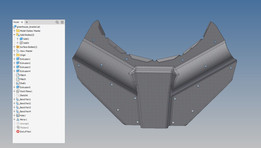
Here is a part made generally to my suggestion. Since I don't have your part dimensions there are some areas that don't look quite correct.

And the flat layout that results from flattening.

This shows the stretching and compression that comes from flattening. This is why you CAN'T use the sheet metal environment.


If you don't receive the email within an hour (and you've checked your Spam folder), email us as confirmation@grabcad.com.