

How to Constrain a Driveshaft in Inventor 2013

Hey guys, I am working on a model rc car and I am having some problems constraining a drive shaft. I believe it is called a dogbone type of shaft and I am trying to constrain it into the cup. I attached a picture of what I am trying to do. I cannot seem to get both sides constrained properly because they are not directly in line and are not level. The shaft will fit between them , but I just cant seem to constrain it there. Thanks for any help.
8 Answer


did you try tangent?

Use Tangent insert, but also use the plans on both parts of IPTs with mates.
I tried tangent and it wouldn't work. I'm not sire what you mean by mates with planes.
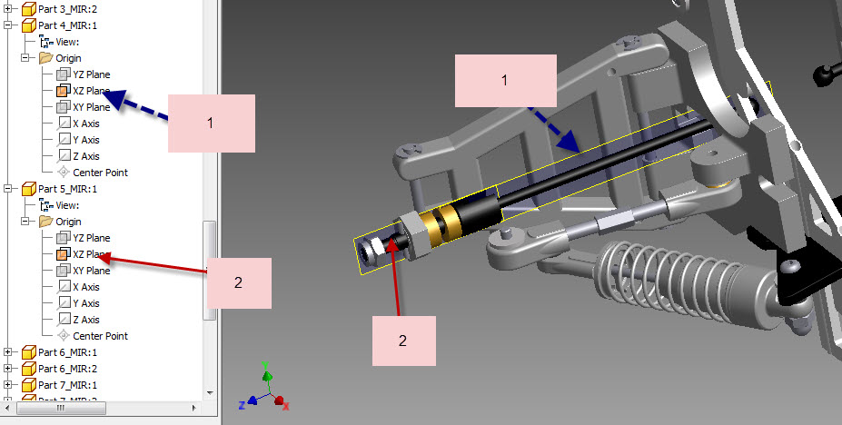
There is a correct way and a wrong way to make an IPT. If you do it the correct way you will always have the 3 plans run right through the middle that gives you an extra 3 ways to constraint to other parts. Unless you need to use the planes for other reasons and help with other stuff. When making an IPT put great though into what it is connecting to rather than just modelling it.....
Anything cylinder should always be a revolve (( good practise rather than a circle extruded...... anything with a hole should always be used by the hole tool and not a circle extruded... etc etc etc..... It is just good working practise and then there is a plans that can help out in many ways also with constraints.
I have uploaded an image for you to see what I mean and also the link to the model if you are having props with anything else for your RC car...
please give me a little PM when you have finished your RC car as I am a big fan of them and it would be appreciated thank you //Handshake
RC Car Front & Back Suspension with Nitro Engine --- suspension
Hot Rod ---- Shell for the RC car
:P
Have a great day and please feel free to PM me if you need any more help with modelling if I can I shall
//Handshake
:P

I'm stupid about building a gap between the surfaces of the cup cup by cup, each line is limited to disobey I have not tried but smarter people admonishing.
Ok thanks guys I will try those and I'll send you a PM when I finish the RC

