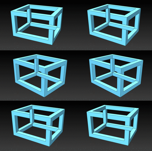
Tutorial: How to create an optical illusion similar to M.C. Eschers cuboid with central perspective in SolidWorks and show design intent

The model to the tutorial you can find here: Optical illusion with central perspective
-
Step 1:
One way to create an optical illusion with a cuboid consisting of girders is, to cut the girders next to the camera-position exactly so, that the girders in the background seem to be in the foreground.
-
Step 2:
To do so with a central perspective, you have to connect the construction of the model with the camera and this will be the result:

-
Step 3:
First define the optical axis for the later positioning of the camera.
In a 3d-sketch create a Y-Axis (I named it “3D-Y-Axis_Endpoint_optical-Axis”) with a certain distance to the origin in X- and Z-direction.
-
Step 4:
Then create a plane (I named it “Plane View-Direction”) which is determined by the Y-Axis and its angle to the right plane.

-
Step 5:
On this plane you sketch the optical axis with an angle to the top plane, an offset from the top plane to the lower endpoint and a certain distance to the upper endpoint.
The upper endpoint will be the position of the camera.
Now you have an optical axis defined by one point and two angle which you can position free in the space of your model.
-
Step 6:
Now sketch the base-rectangle of the cuboid on the top plane with the origin as the center of this rectangle. Then create an offset to this rectangle with the width of your girders. I assume that you want all girders to have a quadratic profile with the same thickness (but this is not necessary).
Then extrude the sketch to the height of the cuboid.
-
Step 7:
Add two cuts to the body using the offset feature.
I linked every offset dimensioning to a shared-value named “Thick_1”, so I can change all girders at one click.
-
Step 8:
Now you have to cut the girder next to the camera point.
Create a new 3d-sketch and place 4 points on the edges of the front-girder and 4 points on the edges of the back-girder which determine the contour of the cut seen from the camera-point as shown in figure below.
You can place the points somewhere on the edges - the later construction-line will fix them.Draw 4 construction lines from the camera-point through the particular points and make them coincident to the points.
(Be patient – it may help to switch off “Automatic relations” in the SWX Options Menu…)
Close the sketch, it is now fully defined.
-
Step 9:
Place a sketch on the inner face of the front-girder and draw a rectangle. Pierce the edges of the rectangle to the beams of the 3d-sketch you created before.
Place a sketch on the outer face of the front-girder (next to the camera-point) and draw a rectangle. Like in the sketch before, pierce the edges of the rectangle to the beams of the 3d-sketch.

-
Step 10:
Make a loft-cut from rectangle 1 to rectangle 2.

-
Step 11:
Cut the second girder in the same manner.
Note: In this example it is only necessary to construct two diagonal beams for the rectangles. You can draw the rectangles witch horizontal and vertical lines and pierce only the vertical points to the boundary-beams.
The central-perspective does not distort angles!
-
Step 12:
Now you can add a camera-view to your model.
For the camera-position choose the upper endpoint of the optical axis.
For the target-point choose the other endpoint of the optical axis.
-
Step 13:
Now adjust the model, so that it fits into the picture.
You can modify the following parameters without disturbing the optical illusion:
Camera:
Rotation
Focal-lengthModel:
Every parameter defining the optical axis.
Even a changing of the dimensions of the cuboid will not disturb the optical illusion.Note: The distance to the camera-position determined in the sketch of the optical axis corresponds to the focal-length of the camera view.
The perspective distortion is independent of the focal length!
I suggest choosing a fixed focal-length of the camera (e.g. 50mm) and adjusting the optical axis, so the cuboid fits into the picture.To adjust the model, split the screen in two views with “Window -> Viewport -> Two View – Vertical” and assign the camera to the right view.
Now you can change the parameters of the cuboid (optical axis and geometry) in the left window and can watch the result in the right window.
-
Step 14:
To show that the optical illusion remains even if you change the position of the optical axis, I animated the cuboid by panning the axis around the Y-axis.
How to animate this, could be another tutorial…Have fun…


