Learn about the GrabCAD Platform
Get to know GrabCAD as an open software platform for Additive Manufacturing
Visit our new homepage
Home
Control
Shop
Streamline Pro
Partner Program
Print
Community
Log in
Library
Challenges
Groups
Questions
Tutorials
Engineers
Blog
Log in
Learn from thousands of free Tutorials.
New user?
Join the community
or
log in.
Tutorials
Most liked all time
Recent
Most liked
Most viewed
Most commented
This week
This month
All time
Category
Design & CAD
Modeling
Drafting
Assemblies
BOM
Dimensioning / Tolerancing
Translations
Manufacturing & CAM
3D Printing
Tooling
NC Machining
Composites
Measurement / Inspection
Simulation & CAE
FEM
CFD
Kinematics
Process Simulation
Engineering Fundamentals
Theory
Process
Standards
Other
Software
Snagit
Alibre Design
ArchiCAD
AutoCAD
AutoCAD Electrical
Autodesk 3ds Max
Autodesk Alias
Autodesk Inventor
Autodesk Maya
Autodesk Revit
Autodesk 123D
BricsCAD
Bentley MicroStation
BlenderCAD
BobCAD-CAM
CATIA
Delmia
DraftSight
FreeCAD
Femap
Fusion 360
Geomagic Design
IronCAD
JT
Kompas-3D
KeyCreator
KeyShot
Lagoa
Luxology
Mastercam
Moi3D
NX Unigraphics
OBJ
Onshape
OpenSCAD
Parasolid
Powermill
Powershape
Pro/Engineer Wildfire
PTC Creo Parametric
PTC Creo Elements
Rhino
SpaceClaim
SOLIDWORKS
solidThinking Evolve
Solid Edge
SolidFace
STEP / IGES
SketchUp
STL
TopSolid
TinkerCAD
T-Flex CAD
TurboCAD
VectorWorks
ViaCAD 3D
VRML / WRL
ZW3D
Rendering
GrabCAD Print
GrabCAD Community
GrabCAD Workbench
Text file
3D Manufacturing Format
Cinema 4D
Other
Skill level
All levels
Beginner
Intermediate
Expert
component
×
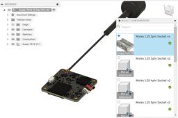
FUSION360 Configurations Tutorial for parts insertion into design
Riley Entropy
in
Assemblies
19
0
Beginner
Turn a model into a configurable model so when you go to insert the part into a design, it will give you a menu where you can select the specific plug from a single file without having 10 individual plugs floating around in a folder :) Things I use this method for: Batteries of varying mAh, screws and standoffs of varying length, plugs, sockets, IC's, etc.
Fusion 360
component
insert
parts
configuration
configurable
Ball Bearing
Pattabiraman Rajakumar
in
Modeling
9
0
Beginner
A ball bearing is a type of rolling-element bearing that uses balls to maintain the separation between the bearing races. The purpose of a ball bearing is to reduce rotational friction and support radial and axial loads. It achieves this by using at least two races to contain the balls and transmit the loads through the balls. Choosing the correct type of bearing during the design stage is crucial to ensure that your machine works safely and efficiently. It is therefore important to consider all operational parameters, such as the dimensions, rotational speed, material, lubrication/seals and the required service life, when choosing the correct bearing.
SOLIDWORKS
design
component
bearings
ball
modelling
3d
Modeling Chain in SolidWorks
Usman Akhtar
in
Assemblies
7
0
Intermediate
https://youtu.be/fj_vtctRXa8
SOLIDWORKS
component
chain
tutorial
solidworks
Design of a Machine Component | CAD | SolidWorks | Machine Design | Engineering | Basic Tutorial
Karthik B D
in
Modeling
6
0
Beginner
The machine component is designed with solidworks software. Comment your feedback and suggestions. #design #engineering #mechanicalengineering #CAD #machinecomponent #solidworks #machinedesign #software #designer #CSWA #CSWP #CSWE #modeling #cadmodel #Solidworksbasics #tutorial #training
SOLIDWORKS
cswa
component
basics
design
engineer
solidworks
cad
machinedesign
[VIDEO] Flange Bearing
Dono Cre'
in
Modeling
5
0
Beginner
In this tutorial I will share about how to create a Flange : 4 Bolt Bearing (Sample UCF 210) design using the Autodesk Inventor software with various features such as: ~ 2D Sketch ~ Extrude ~ Circular Pattern ~ Fillet/Chamfer ~ Revolve ~ Assembly ~ Add Bolt ~ etc.
Autodesk Inventor
autodesk
by
step
assembly
component
bearing
tutorial
inventor
SolidWorks Tutotorial: Fly Tying Vise Modeling | Mechanical Tools & Component Design | Tech Hawk
Tech Hawk
in
Design & CAD
4
0
Intermediate
In this video, Tech Hawk shows you how to model a Fly Tying Vise in SolidWorks. A Fly Tying Vise is an important tool. The principal purpose of a fly-tying vise is to hold a hook securely. In this tutorial, we have prepared a sets of detail drawing of all parts and components of Fly Tying Vise and then made an assembly file. . 00:00 Part 1: Pedestal Base 03:45 Part 2: Pedestal Housing 07:30 Part 3: Pedestal 10:30 Part 4: Main Housing 15:50 Part 5: Rotating Housing 24:05 Part 6: Jaw Shaft 30:20 Part 7: Handle Cam 38:40 Part 8: Adjustment Knob 42:00 Part 9: Nut 43:20 Assembly . We hope this video can help you to practice with SolidWorks software ans make you introduced with some of the commands and features of SolidWorks. We all know that, SolidWorks is a solid modeling computer-aided design and computer-aided engineering computer program. The software is then used for design and building of mechanical, electrical, and software elements. This is getting more and more important nowadays. . Follow Tech Hawk: Facebook: https://www.facebook.com/TechHawk7 Blog: https://techhawk7.blogspot.com/ Twitter: https://twitter.com/techhawk7
SOLIDWORKS
design
vise
tying
fly
tools
component
mechanical
tutorial
hawk
tech
solidworks
Autodesk Fusion 360 Tutorial - How to Insert Standard Spur Gear Component
Ardi Noerpamoengkas
in
Modeling
3
0
Intermediate
This tutorial is about how to insert standard spur gear component on Autodesk Fusion 360. This feature was updated on June 4, 2019.
Fusion 360
modeling
component
spur
gear
autodesk
fusion360
cad
[VIDEO] Bicycle Stem
Dono Cre'
in
Modeling
3
2
Beginner
In this tutorial I will share about how to create a Bicycle Stem design using the Autodesk Inventor software with various features such as:
Autodesk Inventor
component
stem
bicycle
tutorial
inventor
autodesk
ZWCAD Tips | Use Block Attribute to create a customized component library
Iris Chan
in
Drafting
2
1
Beginner
Want to access your frequently used components more quickly? In addition to a library of standard parts, ZWCAD offers Block Attribute for designers and engineers to customize component blocks and create their own component libraries. This function can considerably reduce repetition and enhance your work efficiency.
ZW3D
component
block
drafting
zwcad
Solidworks Tutorial for Beginners | Designing a basic Hub | Solidworks with Kabir
Pradyumn Tiwari
in
Modeling
2
0
Beginner
In Episode 7 of "Solidworks with Kabir" we are going to design a Hub which is a very easy to follow design. Do write down your suggestions and comments in the section below and let me know how you liked this video. Also, please do ask your queries over there, Happy to help! To support me in my journey feel free to like Like/Comment/Subscribe/Share these videos, they mean a lot. Reach out to me here: Email: pagekabir@gmail.com Instagram: https://www.instagram.com/kabir8.24 Website: https://www.kabir.page/ Linkedin: https://www.linkedin.com/in/pradyumn824/
SOLIDWORKS
beginners
component
fixture
hub
tutorial
solidworks
Design a Piston Utilizing solidworks
Hafiz Ali Islami Koniago
in
Modeling
2
0
Intermediate
In this video i show you how to make a Piston in Solidworks. hope this video will help you to design use solidworks Just enjoy it, and like it.. Thanks For Watching Follow my Instagram @thirdkoniago if you want to get more information https://www.instagram.com/thirdkoniago/
SOLIDWORKS
tutorial youtube
step by step
engine
motor
design a piston
make a piston
component
piston
[VIDEO]Create a catalog using Component Family CATIA 3DXP
Maxime Chagnot
in
Modeling
1
0
Intermediate
Here is a tips video showing you how to create a catalog using a component Family. Create a Part with several parameters and link it to a design table with Excel. Then Create a Component Family that will be instantiated into a catalog. Open the catalog in an assembly and add your Catalog Components!
CATIA
template
plm
catalog
family
component
3dexperience
enovia
catia
[video] Verifying hardware and update GPU driver 3DExperience
Maxime Chagnot
in
Other
1
0
Beginner
Hello all, In this 2-min tuto video you will learn how to check if you hardware is certified by Dassault Systèmes. You will see if your GPU is compatible with CATIA V5, V6 and 3DExperience. If so, you will get a link that goes directly to the GPU driver download link. If not, it does not mean that you cannot run the software, but it means that the support cannot help you if you are having troubles or bugs, since the hardware is not certified with the software. Access the certification list here: https://www.3ds.com/support/hardware-and-software/ Please Like, Comment, Share and Subscribe :)
software
component
verified
certified
hardware
gpu
3dexperience
catia
Component interface - Automatic placement definition
Vladimir Palffy
in
Assemblies
1
0
Beginner
In this tutorial, you can learn - How to place objects automatically How to define component interfaces and not place objects one by one and always select the same references.
PTC Creo Parametric
tutorial
creo
interface
component
Helical Spring in CATIA V5
Ameya Kate
in
Modeling
1
1
Beginner
The helical springs are made up of a wire coiled in the form of a helix and are primarily intended for compressive or tensile loads. In this tutorial a simple way to create helical spring using CATIA is shown.
CATIA
mechanical
parts
modelling
component
1
2