Learn about the GrabCAD Platform
Get to know GrabCAD as an open software platform for Additive Manufacturing
Visit our new homepage
Home
Control
Shop
Streamline Pro
Partner Program
Print
Community
Log in
Library
Challenges
Groups
Questions
Tutorials
Engineers
Blog
Log in
Learn from thousands of free Tutorials.
New user?
Join the community
or
log in.
Tutorials
Most liked all time
Recent
Most liked
Most viewed
Most commented
This week
This month
All time
Category
Design & CAD
Modeling
Drafting
Assemblies
BOM
Dimensioning / Tolerancing
Translations
Manufacturing & CAM
3D Printing
Tooling
NC Machining
Composites
Measurement / Inspection
Simulation & CAE
FEM
CFD
Kinematics
Process Simulation
Engineering Fundamentals
Theory
Process
Standards
Other
Software
Snagit
Alibre Design
ArchiCAD
AutoCAD
AutoCAD Electrical
Autodesk 3ds Max
Autodesk Alias
Autodesk Inventor
Autodesk Maya
Autodesk Revit
Autodesk 123D
BricsCAD
Bentley MicroStation
BlenderCAD
BobCAD-CAM
CATIA
Delmia
DraftSight
FreeCAD
Femap
Fusion 360
Geomagic Design
IronCAD
JT
Kompas-3D
KeyCreator
KeyShot
Lagoa
Luxology
Mastercam
Moi3D
NX Unigraphics
OBJ
Onshape
OpenSCAD
Parasolid
Powermill
Powershape
Pro/Engineer Wildfire
PTC Creo Parametric
PTC Creo Elements
Rhino
SpaceClaim
SOLIDWORKS
solidThinking Evolve
Solid Edge
SolidFace
STEP / IGES
SketchUp
STL
TopSolid
TinkerCAD
T-Flex CAD
TurboCAD
VectorWorks
ViaCAD 3D
VRML / WRL
ZW3D
GrabCAD Print
Rendering
GrabCAD Community
GrabCAD Workbench
Text file
3D Manufacturing Format
Cinema 4D
Other
Skill level
All levels
Beginner
Intermediate
Expert
excel
×
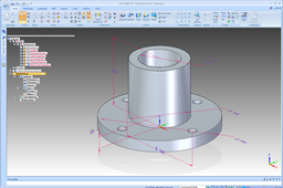
Designing a Hirth Spline
Tjerk de Graaff
in
Theory
27
10
Beginner
Solidworks + Excel instruction on how to design a Hirth Spline. Background on Hirth Splines: https://en.wikipedia.org/wiki/Hirth_joint The basic idea of a Hirth spline / Hirth Joint is that the whole geometry is defined from a combination of a single reference point and a grinding/cutting geometry. Two Hirth splines with the same basic tooth geometry will match to form a secure joint that can transfer torque and allows for accurate alignment of parts. Hirth splines and joints are often used in turbomachinery to accurately align various shaft parts and transfer torque.
design
excel
solidworks
transfer
torque
joint
spine
hirth
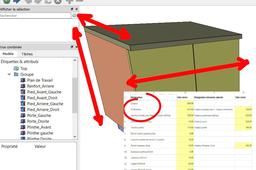
FreeCAD parametric 3d drawing
Christie S
in
Modeling
10
0
Beginner
3D drawing driven by a data sheet. Example : creating a kitchen cabinet furniture driven by a Spreadsheet.
FreeCAD
data
sheet
excel
freecad
Tutorial - How to drive a Solid Edge model from Excel
Grant Holohan
in
Design & CAD
8
2
Beginner
Here's how...
Solid Edge
table
link
part
variable
solid
edge
synchronous
tutorial
excel
variables
Solidworks Design Table Formulas
Interactive CAD & Tech (Chris)
in
Modeling
5
0
Beginner
This is a video tutorial of how to model and use Formulas in Design Tables Design Table Basics Video Tutorial https://www.youtube.com/watch?v=pk74gWNCbQw&t=0s
SOLIDWORKS
excel
formulas
tables
design
solidworks
Aircraft Wing NACA4412 Tutorial Aerospace
Vishal Bharat Patil
in
Modeling
5
0
Intermediate
Designed a Aerofoil shaped Wing of an Aircraft using points generated from excel sheet. Its 4K video that helps one to get the accurate content for desiging the parts..! The main motto is to develop the skills of Engineers. Aircraft Wing NACA4412 Tutorial Link :: https://youtu.be/3mKKGCEO-z4
CATIA
symmetric
drawings
expert
v5
aerofoil
drawing
sheet
excel
tutorial
aerospace
naca4412
aircraft
wing
catia
Tutorial: how to model a gearwheel with teeth with involute shape
Ferro
in
Modeling
5
0
Expert
The model and the excel file related to this tutorial are available here:
Solid Edge
part
table
excel
gear
SOLIDWORKS - Making SolidWorks Makro with ChatGPT ⌨️| Advanced
NonCad Keys
in
Modeling
4
2
Intermediate
Hi guys, in this video I'm going to show you how to create an automatic bolt model with a SolidWorks macro. Thanks to this macro I have developed, you will be able to automatically determine parameters using the Excel database and quickly model bolts of different sizes. Our macro is integrated using the ChatGPT artificial intelligence model to make sense of text-based commands and perform the necessary operations in the SolidWorks environment. This greatly automates the design process, saving you time and minimizing errors. In our video, I will first explain step by step how to get the parameters in our Excel database and how our macro works. As a result, you will be able to create bolt models of different sizes and specifications. You will also discover the potential of the AI-based approach in design processes and see how you can use it in your own projects in the future. If you want to speed up your design processes and increase productivity in SolidWorks, this video is for you! Start watching now and discover how our macro can help you. Don't forget to like the video and subscribe to our channel so you don't miss any similar content. Video Link: https://ytbe.one/ksOW4Sap6So
SOLIDWORKS
macro
openia
chatgpt
excel
solidworks
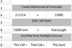
FreeCAD Spreadsheets - The Basics
Sar Dar
in
Design & CAD
3
0
Beginner
An introduction to using FreeCAD spreadsheets.
FreeCAD
formula
bom
math
csv
excel
chart
table
spreadsheet
How to import points from MS Excel in NX?
Hegedűs György
in
Design & CAD
3
4
Beginner
Use these scripts to import 3D coordinates from MS Excel file into NX model (unfortunately sample script and files attachments not allowed).
NX Unigraphics
excel
nx
import
journal
Importing Airfoil from XFLR5 and Auto-Generating Wings in Solidworks
Harvick Tang
in
Modeling
1
1
Intermediate
Video: https://www.youtube.com/watch?v=c_QEEPGUxDg In this tutorial, I will show you how to take an existing aircraft model in XFLR5 and regenerate new wings in Soildworks without editing any features. Required Software: XFLR5 Excel Solidwokrs Required Files: Example Aircraft.xfl - https://drive.google.com/open?id=1Hzz-hu-xgjX3AFN-c7iVGr3h0-pZCJxk XFLR5 to Solidworks Wing Importer.xlsx (Updated) - https://drive.google.com/open?id=1s5VodhyzljYV3vjOD-Ng-lpR-62zMSUp Wing Template.SLDPRT (Updated) - https://drive.google.com/open?id=154oFGNtYu2lWg4jG4Y9MhWufuqD4wra2 XFLR5 Tutorial - https://www.youtube.com/watch?v=P6AZTxZkojo
SOLIDWORKS
excel
solidworks
wings
generating
auto
xflr5
airfoil
tutorial
Create a Product Table - CATIA R19x
Maxime Chagnot
in
Modeling
1
0
Beginner
Hello everyone, In this new tutorial you will learn, how to create a product table in an assembly. It allows you to create different configuration in a product. You will have access to an Excel sheet and decide for each configuration to keep a part (as "true) and remove a part (as "false"). Hope you will enjoy the video! Find the models on these Grabcad links: - https://grabcad.com/library/room-with-3-configuration-1 - https://grabcad.com/library/plate-with-configurations-1 Please Like, Comment, Share and Subscribe :D
CATIA
assembly
excel
configuration
table
product
3dexperience
catia
Why is thickness not updating in a Sheet Metal reducer part?
Dan Novak
in
Design & CAD
0
0
Beginner
I'm not sure if this is the "correct" answer, but I got it to work by adding Thickness@Sheet-Metal1 to the table and changing it along with PL Thick.@Lofted Bends1. See screen caps.
SOLIDWORKS
sheetmetal
excel
thickness