

Single Eye End- Knuckle Joint Part 2

Learn, how to draft Single Eye End, a part of Knuckle Joint, by using Creo Parametric.
-
Step 1: Sketch-1
Select the plane and click on 'Sketch'.
Select 'Circle' and draw a circle of 60mm diameter.

Click on 'OK'.
-
Step 2: Extrude-1
Click on 'Extrude'.
Extrude the sketch by 36mm.

Click on 'OK'.
-
Step 3: Sketch-2
Select the right plane and click on 'Sketch'.
Select 'Rectangle' and draw of rectangle of lenght-120mm and breadth-33mm.

Click on 'OK'.
-
Step 4: Extrude-2
Click on 'Extrude'.
Extrude the sketch by 33mm.

Click on 'OK'.
-
Step 5: Sketch-3
Select the end surface of the previously extruded feature and click on 'Sketch'.
Select 'Circle' and draw a circle of 30mm.

Click on 'OK'.
-
Step 6: Extrude-3
Click on 'Extrude'.
Extrude the sketch by 40mm.

Click on 'OK'.
-
Step 7: Sketch-4
Again select the same surface and click on 'OK'.
Click on 'Palette' and select Octagon.
Draw a Octagon with Medium Diagonal of 40mm.

Click on 'OK'.
-
Step 8: Remove Material-1
Click on 'Extrude'.
Extrude the sketch by 45mm and select 'Remove Material'.

Click on 'OK'.
-
Step 9: Sketch-5
Select the top plane and click on 'Sketch'.
Select 'Circle' and draw a circle of 30mm.

Click on 'OK'.
-
Step 10: Remove Material-2
Click on 'Extrude'.
Extrude the sketch by 18mm on both sides (36mm total) and select 'Remove Material'.

Click on 'OK'.
-
Step 11: Fillet/Round
Click on 'Round'.
Provide fillet or roundness wherever required of appropriate radius.


Click on 'OK'.
-
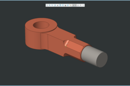
Step 12: Final Part- Single Eye End
Final Part:

