Learn about the GrabCAD Platform
Get to know GrabCAD as an open software platform for Additive Manufacturing
Visit our new homepage
Home
Control
Shop
Streamline Pro
Partner Program
Print
Community
ログイン
Library
Challenges
Groups
Questions
Tutorials
Engineers
Blog
ログイン
Learn from thousands of free Tutorials.
New user?
Join the community
or
log in.
Tutorials
Most liked all time
Recent
Most liked
Most viewed
Most commented
This week
This month
All time
Category
Design & CAD
Modeling
Drafting
Assemblies
BOM
Dimensioning / Tolerancing
Translations
Manufacturing & CAM
3D Printing
Tooling
NC Machining
Composites
Measurement / Inspection
Simulation & CAE
FEM
CFD
Kinematics
Process Simulation
Engineering Fundamentals
Theory
Process
Standards
Other
Software
Snagit
Alibre Design
ArchiCAD
AutoCAD
AutoCAD Electrical
Autodesk 3ds Max
Autodesk Alias
Autodesk Inventor
Autodesk Maya
Autodesk Revit
Autodesk 123D
BricsCAD
Bentley MicroStation
BlenderCAD
BobCAD-CAM
CATIA
Delmia
DraftSight
FreeCAD
Femap
Fusion 360
Geomagic Design
IronCAD
JT
Kompas-3D
KeyCreator
KeyShot
Lagoa
Luxology
Mastercam
Moi3D
NX Unigraphics
OBJ
Onshape
OpenSCAD
Parasolid
Powermill
Powershape
Pro/Engineer Wildfire
PTC Creo Parametric
PTC Creo Elements
Rhino
SpaceClaim
SOLIDWORKS
solidThinking Evolve
Solid Edge
SolidFace
STEP / IGES
SketchUp
STL
TinkerCAD
TopSolid
T-Flex CAD
TurboCAD
VectorWorks
ViaCAD 3D
VRML / WRL
ZW3D
Rendering
GrabCAD Print
GrabCAD Community
GrabCAD Workbench
Text file
3D Manufacturing Format
Cinema 4D
Other
Intermediate
All levels
Beginner
Intermediate
Expert
Design & CAD
×
NC Machining
×
Process Simulation
×
New approach in designing and modelling an Oil pump using Inventor 2016
Ebrahim Abu Has
in
Design & CAD
117
13
Intermediate
Step by step tutorial videos, showing the easy way of modelling an Oil pump using Inventor 2016, how to create the parts, assemble them and drive gears, new approach make use of most Inventor specs, design center with some new tips & tricks ...
Autodesk Inventor
ticks
tips
some
splines
parallel
shafts
keyways
keys
shaft
design
gears
spur
How to design Complete Drone Overview
Rugved Chavan
in
Modeling
90
8
Intermediate
Complete Drone design with 1. raspberry pi 4 extension 2. pixhawk 3. landing gears 4. drone frame 5. telemetry module 6. gps module with stand 7. Battery 3300 mAh 8. antivibrator 9. Brushless Motor (BR4114) Please give it a like.
Fusion 360
fusion360
telemetry
raspberrypi
drone
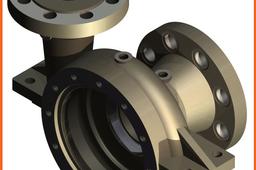
How to model a Centrifugal Pump Body (Spiral construction) using Inventor 2014?
Constantin STANCESCU
in
Design & CAD
76
18
Intermediate
We have to abide by all the conditions from the technical drawing Note: You can watch my live tutorial for modeling this part here: https://youtu.be/yxEAv2p31zw
Autodesk Inventor
centrifugal_pump
inventor_2014
ipt
multi-body
spiral
coil
LEGO - 01 Basic Dimensions & Bricks Explained
dk
in
Modeling
71
9
Intermediate
I get a lot of questions about how I create LEGO parts. This is Part I - The Basics. Most "standard" parts can be created using only simple math. Standard parts consist of square, circular, and angled blocks - regular geometric blocks. I will refer to BrickLink (www.bricklink.com/), but many others use similar methods: Peeron: http://www.peeron.com/ BrickOwl: http://www.brickowl.com/ Brickipedia: http://lego.wikia.com/wiki/LEGO_Wiki etc.
Autodesk Inventor
bricks
dimensions
lego
Convert STL (or OBJ) Mesh to SOLIDWORKS Model (NURBS)
FredSWUG
in
Modeling
69
12
Intermediate
Need to convert an STL (or OBJ) file into a "real CAD model"? There are several tutorials which already exists for this topic. I'm making a new tutorial to give additional information.
SOLIDWORKS
part
convert
model
sldprt
mesh
stl
Cap screws and machine screws
dea
in
Drafting
67
12
Intermediate
Cap screws and machine screws are similar in shape, differing only in their relative sizes. Machine screws are usually smaller in size, compared to cap screws. These are used for fastening two parts, one with clearance hole and the other with tapped hole. The clearance of the unthreaded hole need not be shown on the drawing as its presence is obvious. Figure 5.24 shows different types of cap and machine screws, with proportions marked Cap screws are produced in finish form and are used on machines where accuracy and appearance are important. As cap screws are inferior to studs, they are used only on machines requiring few adjustments and are not suitable where frequent removal is necessary. These are produced in different diameters, upto a maximum of 100 mm and lengths 250 mm. Machine screws are produced with a naturally bright finish and are not heat treated. They are particularly adopted for screwing into thin materials and the smaller ones are threaded throughout the length. They are used in fire-arms, jigs, fixture and dies. They are produced in different diameters upto a maximum of 20 mm and lengths upto 50 mm.
Autodesk Inventor
screw
cap
SOLIDWORKS TUTORIAL : DESIGN A NISSAN GTR.
Rare Mechanic
in
Modeling
61
4
Intermediate
Hey designer, Hope you going well in your designing Journey. I've made a complete step by step tutorial in which you're going to design a 'NISSAN GTR" in solidworks. . Start this tutorial series & enhanced your surfacing skills by completing it.
SOLIDWORKS
tutorial
cardesigning
advancedsurfacing
solidworkstutorial
design
nissangtr
automobile
cad
(VIDEO TUTORIAL) Solidworks Tutorial #155 How to Design a JET GAS TURBINE Assembly (Engine) in Solidworks Easy Design
Praveen Kumar
in
Assemblies
49
9
Intermediate
Full Assembly Jet Gas Turbine Engine . Part Two Available on our YouTube Channel................. I hope you like this Tutorials This Tutorial Made by Request for Collage Students I'm always upload easy way drawing not hard. And unique trick friends. So please Subscribe & Share every Friends.
SOLIDWORKS
mechanical
engineering
rendering
modeling
design
assembly
solidworks
How to make a rendering with SolidWorks
Miguel De Haro
in
Modeling
46
1
Intermediate
How to make a rendering with SolidWorks
SOLIDWORKS
rendering
solidworks
Seat Cowl Modeling
Xray
in
Modeling
43
2
Intermediate
I was asked how to make the my Ducati seat cowl in Catia. Unfortunately, I haven't worked in Catia for years, the model was made in Solidworks. Having worked in ProE, CATIA and Solidworks - though menu pics and verbiage may be different, they and other systems, are all capable of creating the same features with similar steps. I created a simplified PDF that shows the basic - steps taken to create this seat. These steps can be used as a frame work to design a wide variety of parts and on several CAD platforms. There are a lot of ways to do things, hopefully you find some of this useful. The model can be downloaded from GrabCAD. It is named: Ducati 996 / 998 Cafe Race Seat.
SOLIDWORKS
ducati
modeling
how
surfacing
cafe
seat
motorcycle
Solidworks Car Tutorial :Model a NISSAN GTR.
H.J. Bhatt
in
Modeling
42
0
Intermediate
Hey designer, Hope you going well in your designing Journey. I've made a complete step by step tutorial in which you're going to design a 'NISSAN GTR" in solidworks. . Start this tutorial series & enhanced your surfacing skills by completing it.
SOLIDWORKS
solidworks
advancedsurfacing
tutorial
automobile
cad
Fastest way of drawing car rims
Valentino Les
in
Modeling
42
2
Intermediate
Folow these steps to really quickly create awesome looking car rims for any car . Have on mind these rims won't match 1:1 scale because we will use pictures as references. Also these rims will only look good but won't be functional and usable for real life appliance. Only for renders. Goal of this tutorial is to create a good looking car rim as fast as possible.
SOLIDWORKS
wheel
rim
car
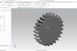
How to create spur gear in Siemens NX?
Hegedűs György
in
Modeling
41
6
Intermediate
This tutorial presents the modeling of an external spur gear in Siemens NX. The detailed modeling process is demonstrated on this video: https://youtu.be/pVPjDyOn6R4 UPDATE: At ~ 2:40 leave the Limit options at default (At Point). See the errata video for the reason: https://youtu.be/PUpdlyQcaOs
NX Unigraphics
gear
spur
LEGO - 02 Building Bricks with Parameters
dk
in
Modeling
39
4
Intermediate
I don't get asked this but it is a very powerful tool and will make your life a lot easier. This also applies to other repetitive parts, not just LEGO bricks, and can be applied with the exact same methods.
Autodesk Inventor
parameters
lego
Chassis Design Using CATIA
Jasper Aaron
in
Modeling
39
1
Intermediate
Chassis Design using CATIA Wireframe > Surface > Solid
CATIA
surface
frame
car
model
supra
advanced
tutorials
modelling
rollcage
catia
using
design
chassis
1
2
3
…
100